 0
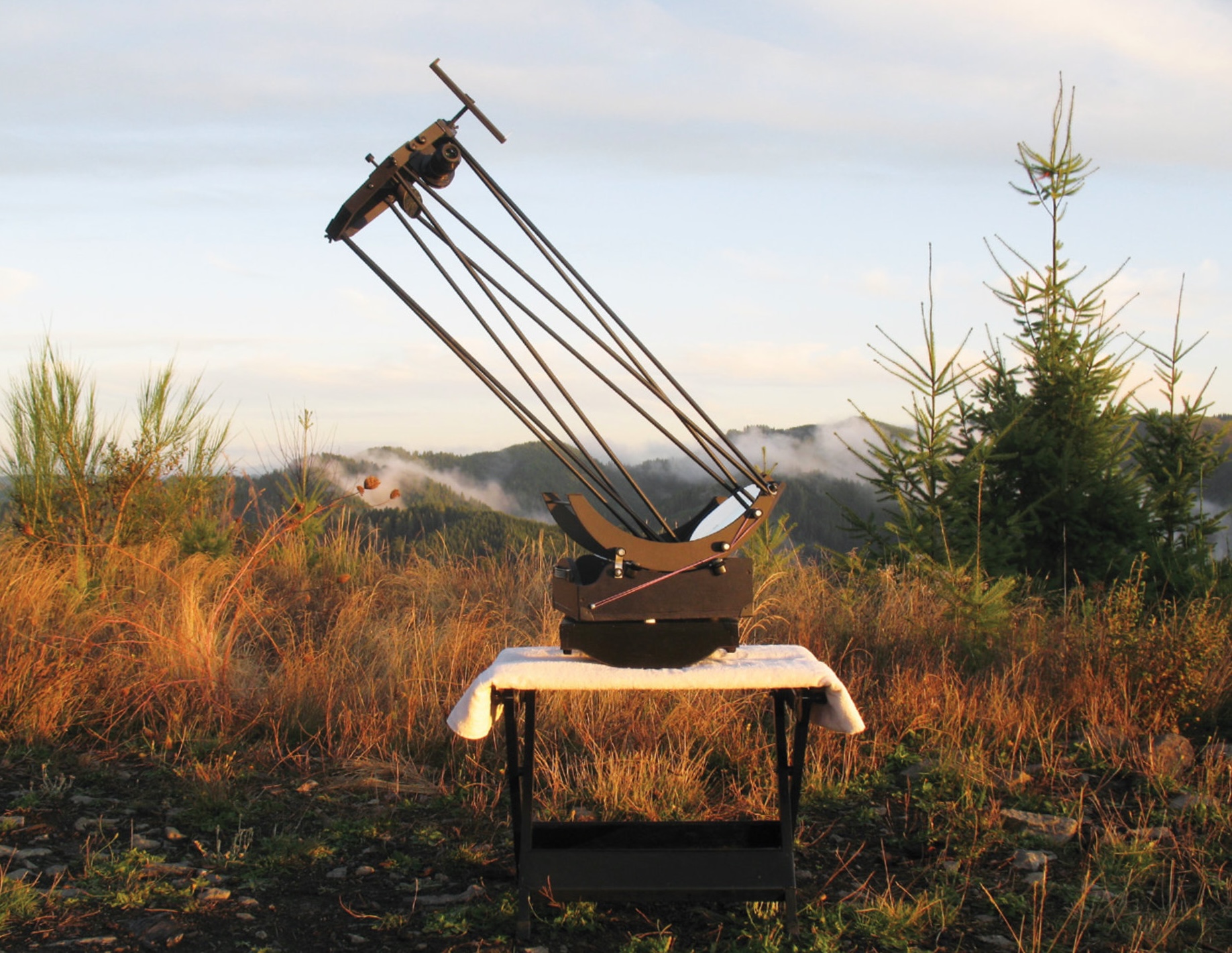
0Here’s a lightweight reflector that fits in your carry-on luggage.
Jerry Oltion
I live in a forest. The only view of the sky I get from my house is a tiny notch above my roof, viewable from my driveway. To make matters worse, my sky is badly light polluted. So every telescope I’ve made has to fit into my car for the drive out of town and be at least tolerably easy to set up and take down in the dark.
I also dream of traveling to the Southern Hemisphere to see the part of the sky inaccessible from my home latitude of 44° north. Somehow, I don’t think I’ll be taking my 121⁄2-inch binocular scope on an airplane, though. Nor do I trust baggage handlers with a classic Dobsonian or even a refractor in a padded case. What I need is a scope with enough aperture to be useful that packs into a box I can carry onboard.
A Seed Is Planted
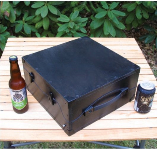
In my October 2016 Astronomer’s Workbench column, I wrote about an amazing travelscope built by Dutch telescope maker Roel Weijenberg. It sported an 8-inch f/4 mirror yet fit into a box only 9.25′′ × 10.5′′ × 3.9′′ on a side — a box made up of the scope’s own ground board and rocker box. The moment I saw it I knew I wanted to build one myself, but it took me several years to do it.
Why so long? I had to work up my courage! So many elements had to fit perfectly with so many others that the entire process seemed fraught with peril. I eventually set to work and kept track of the many design decisions I had to make along the way. It’s those decisions, many of which apply to any telescope-making project, that I want to share with you now. It’s my hope that this story will demonstrate how a methodical approach to telescope making can see you through just about any project. Hopefully it will inspire you to try building a telescope of your own, if not this design (which I wouldn’t recommend as a first-time project) then some other, and it will help you figure out how to make everything work together.
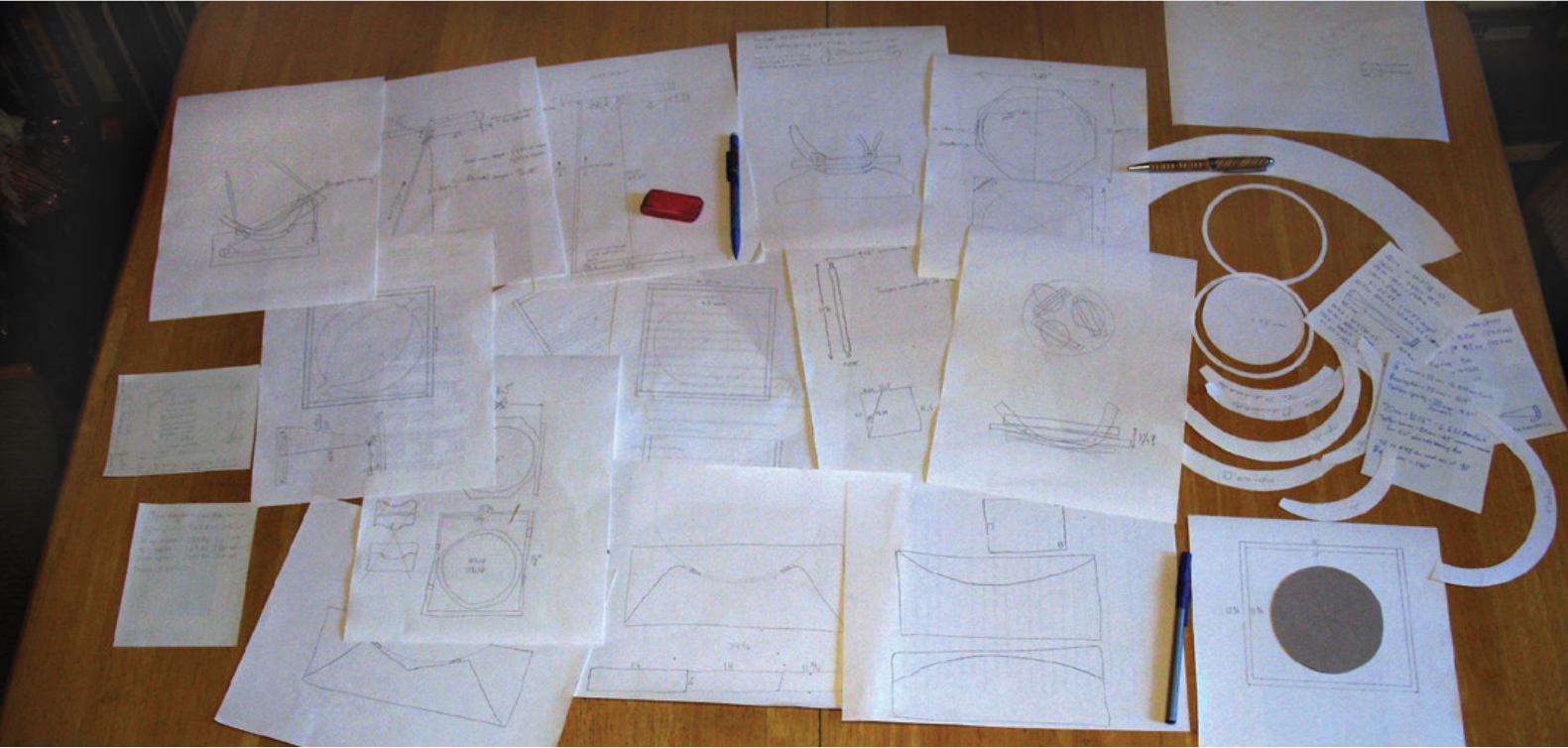
I’m the kind of telescope maker who stands in the shop and stares at my scrap wood pile until I see a piece of plywood that will make a good start, and off I go. This is why a travelscope seemed so daunting — I could just envision making some nifty part that would work fine on a normal scope but wouldn’t fit in the box with everything else. I did way more thinking on this scope than with any of my others, and I even drew a bunch of pencil sketches of the most difficult parts before building them. Even so, I rebuilt a lot of components when I came to others that wouldn’t fit with what I’d already made.
Getting Started
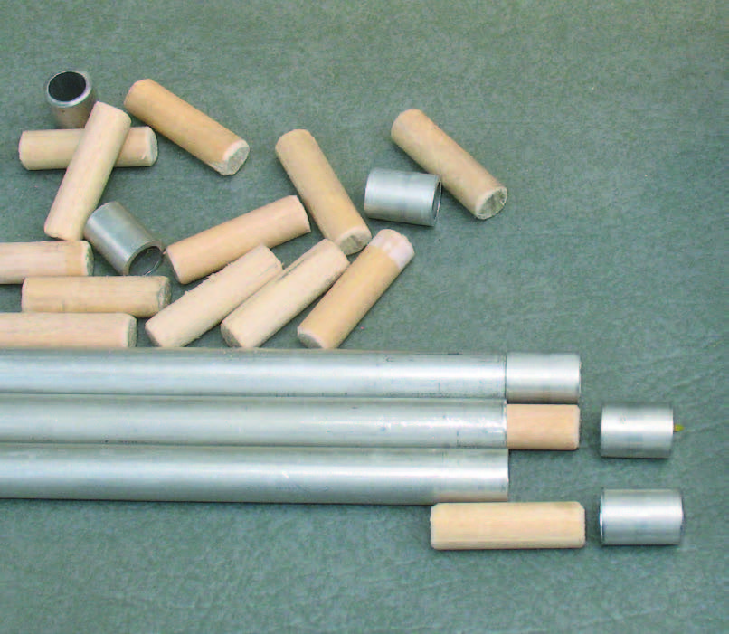
The first design element was the mirror. I had several 91⁄2-inch (240-mm) mirror blanks that I’d gotten through a Cloudy Nights classified ad, so I chose one as the starting point. I already had a bunch of foot-long, 3/8-inch-diameter (9.5-mm) aluminum tubes that I’d bought several years ago in anticipation of building a travelscope, and I figured I would use three sections per truss, which meant three-foot trusses. A little math told me I should make the mirror f/4.
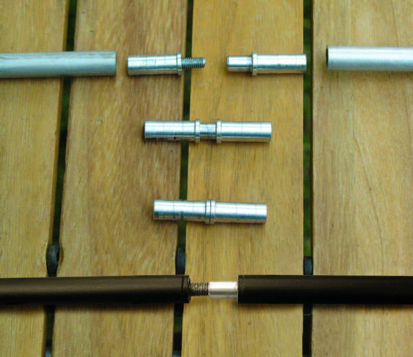
While I ground and polished the mirror, a machinist friend (Hi, Mike Curtin!) made a set of truss connectors for me. They screw together, and the threaded parts stick out half an inch at either end of the tubing, at least for the middle section. That added an inch to the length of the tubes, so I originally figured I’d need one of the box’s interior dimensions to be at least 13′′ to hold the trusses. I had a bunch of 1⁄2′′ Baltic birch plywood left over from other projects, so I decided to build the box out of that, which made the longest outside dimension 14′′.
Jerry Oltion
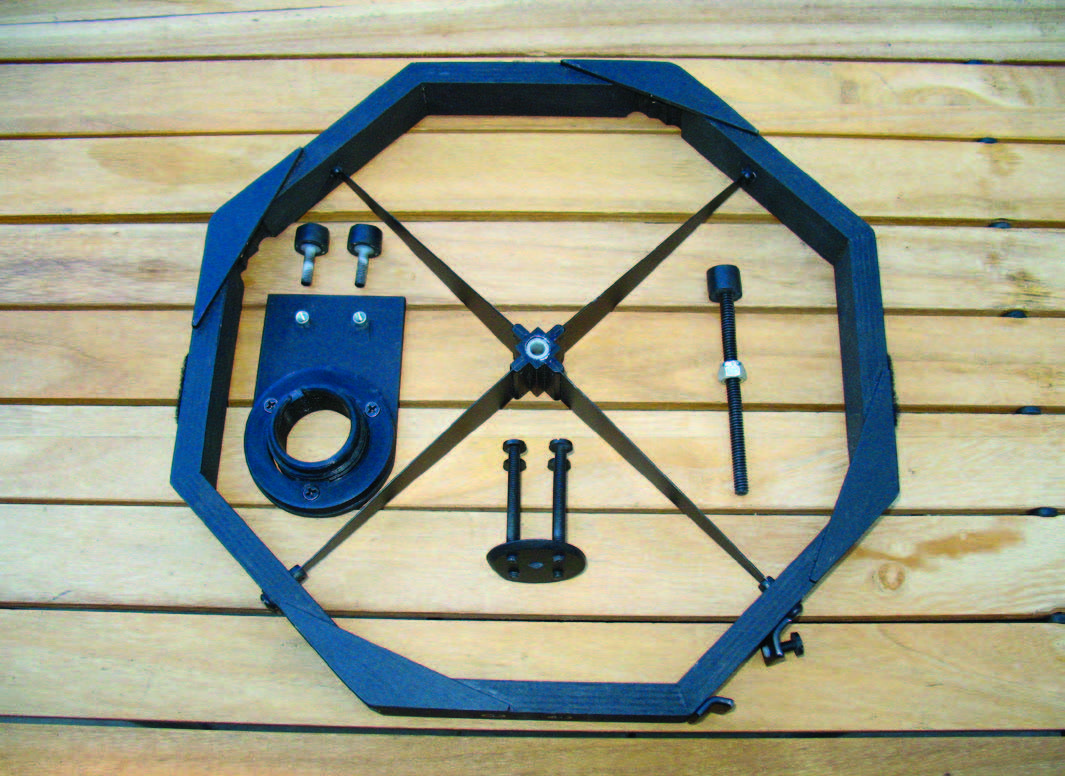
Another dimension was dictated by the size of the secondary ring. I planned to use a 24-mm, 68° eyepiece for my widest field (the best you can do with 11⁄4′′ eyepieces), which would give me a 1.6° true field of view. That meant the secondary ring’s inside diameter needed to be at least 0.9′′ bigger than the mirror to avoid vignetting, so I made the inner diameter 101⁄2′′. Since I figured the ring should be at least half an inch thick to be sturdy enough, that made its outer diameter 111⁄2′′. Add a quarter inch so it would fit easily in the box, and that made the box’s minimum inner dimension 113⁄4′′, and an outer dimension of 123⁄4′′.
I arbitrarily chose to make the box 6′′ high internally to start with, which meant 7′′ high externally. That gave me a box with outside dimensions of 123⁄4′′ × 14′′ × 7′′.
Truss Considerations
To accommodate the mirror’s focal length and the design’s 36-inch-long trusses, I had to mount each pole on top of the mirror cell, rather than on the side of it, and I also had to place the focal plane 7′′ out from the optical axis. That would require a larger secondary mirror than the 11⁄2′′ one I had on hand, but I couldn’t see a better solution . . . until someone pointed out that there was no need to arrange the trusses lengthwise in the box. Instead, I could lay them diagonally, which meant they could be way longer than 13′′. And that meant I could place the focal plane closer to the outside of the secondary ring and use my smaller secondary mirror.
Jerry Oltion
Jerry Oltion
So I added 1⁄2′′ to the end segments of each truss, bringing the total truss length to 37′′ while keeping each segment 13′′ long (including the connectors).
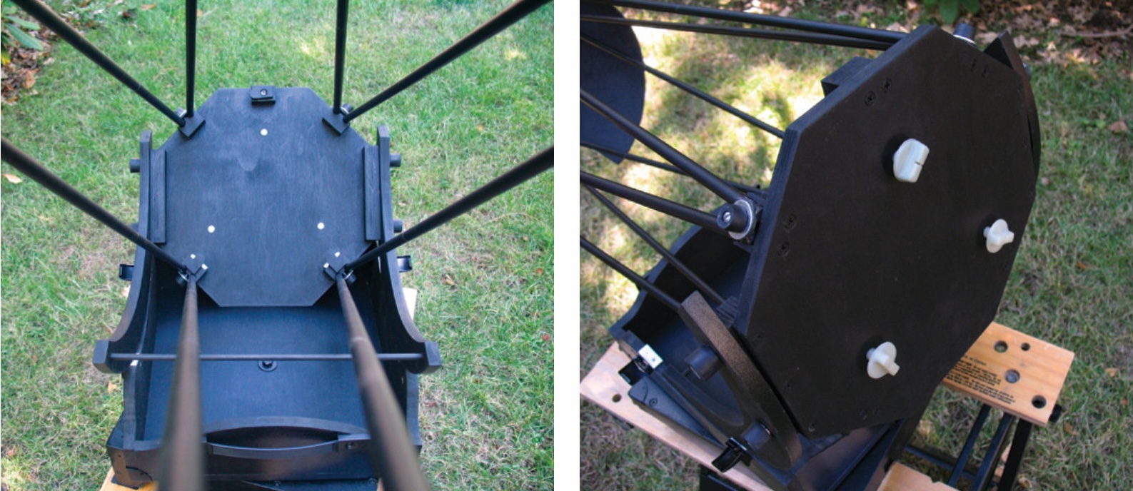
Even with the longer trusses, I still had to attach them to the top of the mirror cell. Of course, the truss connection points also needed to lie outside of the light path. All this meant making the mirror cell larger than the mirror. Fortunately, with the 111⁄2′′ secondary ring dictating the size of the box, I could make the mirror cell 111⁄2′′ across, too, giving me plenty of space for truss mounts.
An octagonal cell gave me flat edges for mounting the altitude bearings and still kept the corners of the box free to store eyepieces. At first, I thought I could make 10′′-radius altitude bearings, which would put the center of rotation very close to the balance point, but when I realized I could store the trusses in the box at an angle, I was able to cut the box down to 123⁄4′′ square, which was a big attraction. Doing that meant I could only use an 8′′ radius on the altitude bearings, though, which would put the scope’s center of rotation below the center of gravity, making the scope top-heavy. That meant I would need some kind of bungee system or counterweight to balance the finished scope.
Because I was making the primary mirror cell octagonal, I made the secondary ring octagonal, too. That let me mount the trusses inside the corners of the octagon, which I think looks nicer than mounting them on the outside.
A Shrinking Rocker Box
I had already made the box 14′′ long but hadn’t made the cut- outs for the altitude bearings in the sides yet, so I still could shorten it. I then had to decide how to cut the seam between the top and bottom halves. The altitude bearings would define part of the seam, but how high should they be? The front of the mirror cell needed to clear the bottom of the box when the scope was aimed toward the horizon, and at the same time I needed to cut low on two corners and on the center of the opposite side so the lid would rest on three points when it served as the ground board. I drew all sorts of funky zigzags, then realized none of them could be cut without leaving big gaps where I would have to drill holes in order to change the angle of a jigsaw blade. I needed to make curvy lines so I could cut them in one smooth go.
Jerry Oltion
Jerry Oltion
Jerry Oltion
Jerry Oltion
I still had to fill the gap between the top and bottom halves of my box with 1/8′′ closed-cell neoprene foam to seal it tight and refine the fit. I glued the foam to the bottom side of the box lid. The foam makes a great vibration damper since this piece serves as the scope’s ground board. I also used a big square of the same foam to make a light baffle opposite the focuser. It’s the first thing in the box when I pack up, and it provides a nice, cushy bed for everything else to rest on.
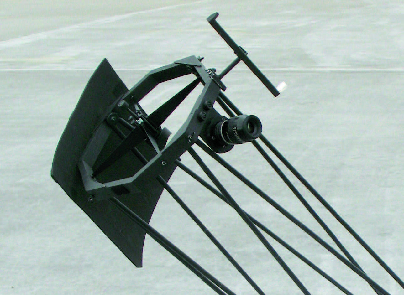
My original focuser design was just a simple push-pull tube like what John Dobson used in his telescopes. But once I figured out exactly where the focal plane was, I had another friend (Hi, Robert Asumendi!) 3D-print a lightweight helical focuser for me. It’s the perfect design for a travelscope, for which space is a precious commodity.
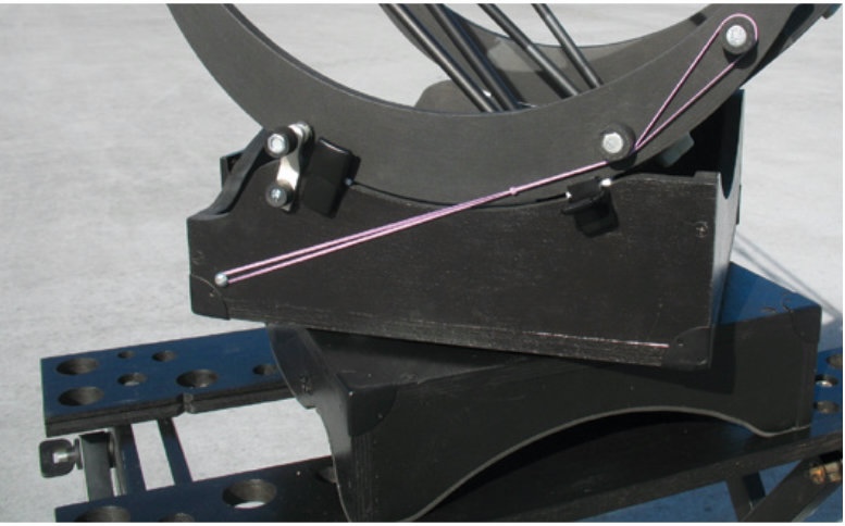
After figuring out the major parts of the scope, I assembled everything and fiddled with its balance. I didn’t want to add unnecessary extra weight to a box I will have to carry through airports, so I experimented with various bungee setups, eventually discovering that two sets of #33 rubber bands tied end to end and used on both sides of the mount worked beautifully. In cold weather rubber bands lose some of their strength, so I carry a bag of extras to fine-tune their pull.
Jerry Oltion
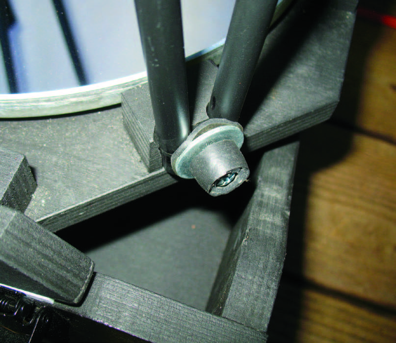
The eyepiece is such a significant portion of the front end’s weight that the scope would head for the zenith whenever I removed one. That meant I needed a clutch system to hold the scope in position. Again, I tried various designs, from wedges to spring clamps to magnets, but I eventually realized that a simple screw on an arm would do. Tightening the screw pushes a piece of grippy rubber against the side of the altitude bearing, and the scope stays put.
Making It All Fit
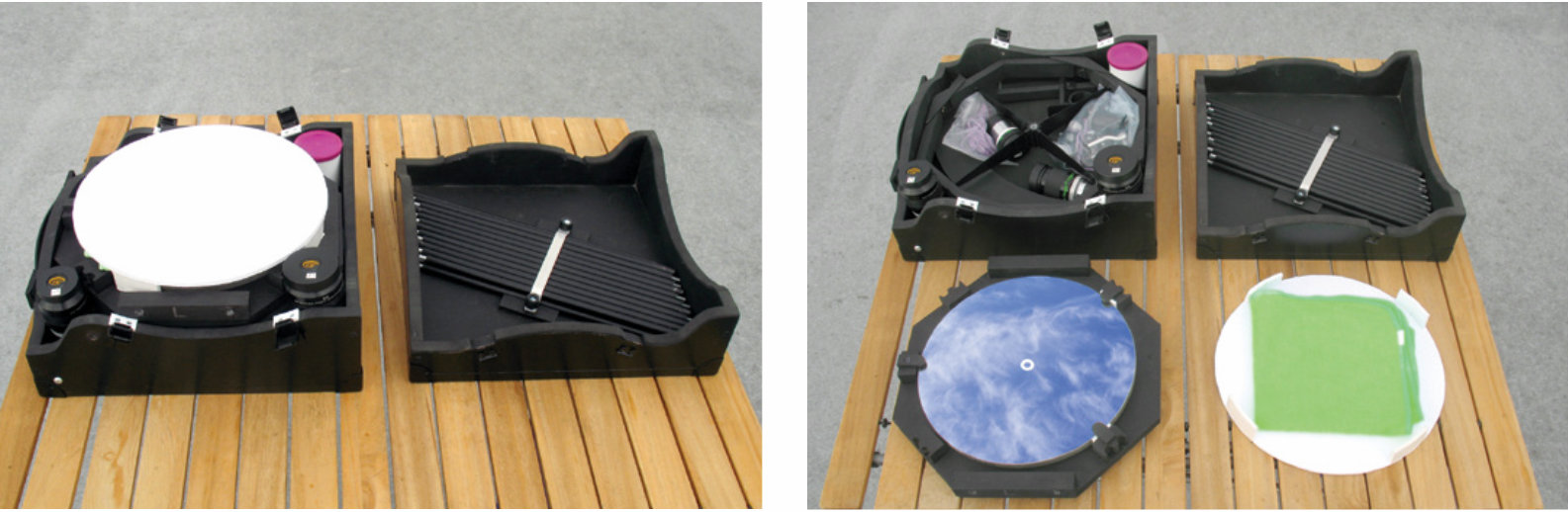
Although the scope was working well, I hadn’t yet figured out how to pack it all in the box. I’d assumed the primary mirror in its cell would go in the bottom, then the secondary cage on top of that, followed by the altitude bearings, with eyepieces in the corners and the focuser disassembled to lie flat inside the arc of the altitude bearings. But that arrangement proved inefficient — 6 inches of internal space vanished pretty quickly. The collimation bolts sticking out the bottom of the mirror box wasted half an inch of depth, and the altitude bearings got in the way of everything. Also, I was worried about all that irregular stuff resting on the primary mirror, even with some padding in between.
Jerry Oltion
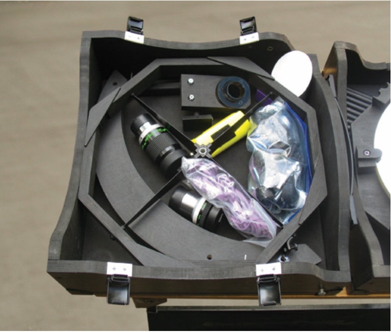
So, I played with other arrangements, eventually realizing I could stack the altitude bearings on top of one another around one side of the box, then put the secondary cage on top of those, and that would leave me four big gaps in between the spider vanes to hold some eyepieces, the focuser, finder, the bag of parts, spare rubber bands, etc. The secondary mirror goes into a form-fit case that sits in the corner opposite the altitude bearings, and everything else packs neatly in between the spider vanes or in the other corners. Two of the eyepieces fit so snugly you’d swear I designed everything around them, but it was just luck.
Jerry Oltion
With everything packed that way I gained so much room I had an extra inch of space between the primary mirror and the trusses (which mount diagonally two layers deep inside the lid). So, I cut the box down to 6′′ high, to its finished dimensions of 123⁄4′′ × 123⁄4′′ × 6′′. That still leaves room for a generous primary mirror cover that fits snugly against the trusses and holds everything tight.
One thing I learned on this project is that travel scopes aren’t simple scopes. In fact, the smaller you make them, the more complicated they become. This scope takes me about 25 minutes to set up, which is 5 minutes longer than it takes to set up my 20′′. But this scope will fit under an airplane seat, which is where I intend to put it . . . on a flight to the Southern Hemisphere as soon as possible.
Jerry Oltion
Further Reading
Many of the telescope-making concepts referenced in this article can be found in The Dobsonian Telescope by David Kriege and Richard Berry, which can be purchased in our online store at shopatsky.com/products/dobsonian-telescope.
This article originally appeared in the April 2022 issue of Sky & Telescope.
About Jerry Oltion
Jerry Oltion writes the Astronomer's Workbench column for Sky & Telescope. He enjoys building his own equipment, be it large or small. He also writes science fiction, and is the most published author in the history of Analog magazine. Visit his website at www.jerryoltion.com

Comments
You must be logged in to post a comment.